Product Description #
The RevPi Core S or RevPi Core SE is a 24 V industrial PC for IIoT and automation projects based on the Raspberry Pi Compute Module 4S. The RevPi is a base module from the Revolution Pi product family. All devices in the Revolution Pi product family are developed in accordance with EN 61131-2.
Components #
|
Note
|
RevPi Core S and RevPi Core SE have the same structure. |
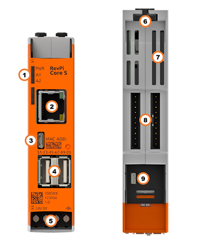
| Position | Component | Application |
|---|---|---|
1 |
3 × status LED |
|
2 |
RJ45 Ethernet |
|
3 |
Micro-USB |
|
4 |
2× USB A |
|
5 |
X4 connector |
|
6 |
2 × locking clip |
|
7 |
Ventilation Slots |
|
8 |
2 × PiBridge |
|
9 |
Micro HDMI |
Compatible RevPi Image
-
RevPi Bookworm Image
-
RevPi Bullseye Image
-
RevPi Buster Image
See: RevPi Images.
Variants #
RevPi Core S #
| Item No.: | RAM | eMMC | Compatible with RevPi Gateways |
|---|---|---|---|
100359 |
1 GB |
8 GB |
Yes |
100360 |
1 GB |
16 GB |
Yes |
100361 |
1 GB |
32 GB |
Yes |
RevPi Core SE #
| Item No.: | RAM | eMMC | Compatible with RevPi Gateways |
|---|---|---|---|
100365 |
1 GB |
8 GB |
No |
100366 |
1 GB |
16 GB |
No |
100367 |
1 GB |
32 GB |
No |
For available variants see Revolution Pi Shop.
Expansion Modules #
The RevPi Core S or RevPi Core SE base module can be expanded by up to 10 expansion modules to create a Revolution Pi system:
| Left side | base module | Right side |
|---|---|---|
|
5 × RevPi I/O module, |
RevPi Core S |
5 × RevPi I/O module, |
5 × RevPi I/O module |
RevPi Core SE |
5 × RevPi I/O module |
Compatible RevPi I/O Modules #
Compatible RevPi Gateways #
RevPi Gateways can only be connected to the system on the far right or far left via a PiBridge plug connector. The RevPi gateways are not supported by the SE models of the Revolution Pi product family.
-
RevPi Gate PROFINET
-
RevPi Gate EtherNet/IP
-
RevPi Gate EtherCAT
-
RevPi Gate PROFIBUS
See RevPi Gateways
Scope of Delivery #
The scope of delivery includes
-
RevPi Core S / RevPi Core SE (base module)
-
X4 connector
-
2 × blind plug for PiBridge/ConBridge
-
Supplement
Mounting and Connecting #
The RevPi was developed for use in a control cabinet. Observe the specifications for the Intended Use and all Safety Instructions.
|
Warning
|
Danger to life due to electrical shock
There is a risk of fatal electrical shock when working on devices in the switch cabinet with 230 V mains voltage. ▷ Operations in the switch cabinet may only be carried out by qualified electricians. ▷ Before carrying out any operations in the switch cabinet, switch off the power supply properly. |
Carry out the mounting and connection in the following order:
-
Mount the RevPi base module and all expansion modules on a DIN rail.
-
Connect the expansion modules via PiBridge plug connectors.
-
Connect all other devices such as sensors and actuators. The interfaces available to you for this can be found in the Structure section.
-
Connect a monitor and a keyboard if you want to operate the RevPi in desktop mode. This is not necessary if you access the RevPi via a network connection.
-
As the last step connect the power supply.
|
Note
|
The RevPi Gateways are not supported by the RevPi SE models. |
Access to the Device #
The RevPi is accessed in two steps:
Install all available updates as soon as the RevPi is connected to the internet, so that the system is always up to date with security-relevant features.
Alternatively, access is possible without a network, see Setting up Desktop Mode.
See also:
Configuration #
The RevPi is configured in two steps:
|
Note
|
Until the RevPi Bullseye Image (04/2024), the RevPi base module is configured via the RevPi Status application. |
-
From the RevPi Bookworm Image (10/2024), the basic configuration of the RevPi devices is carried out via the Cockpit web application:
-
Network configuration, user administration, status and log views can be managed via a browser.
-
In addition to the standard server configuration, the Revolution Pi and Node-RED plugins are also available. These allow you to configure your RevPi base module and easily activate or deactivate the installed services.
-
-
The module configuration of a Revolution Pi system, i.e. a RevPi base module with expansion modules, is carried out via the PiCtory application or, if necessary, directly in the development environment, e.g. via CODESYS.
|
Note
|
CODESYS and PiCtory cannot be used in parallel for configuration. An existing configuration via PiCtory will be overwritten by a configuration via CODESYS. The virtual devices OPC UA Server and MQTT Client can only be used via PiCtory. |
Parameterization #
The following parameters, inputs (INP) and outputs (OUT) can be configured:
RevPiStatus (INP) #
Uses bits to represent different states of the piControl driver.
| Bit | Function |
|---|---|
0 |
piControl driver is running. |
1 |
At least one connected I/O module has not been configured. |
2 |
At least one I/O module has been configured but not connected. The bit is also set if a RevPi Gateway has been configured. |
3 |
An I/O module occupies more or fewer bytes in the process image than specified in the configuration. |
4 |
A RevPi Gateway is connected to the left side of the RevPi. |
5 |
A RevPi Gateway is connected to the right side of the RevPi. |
6 |
The limit value of the first error counter RS485ErrorLimit1 has been reached. |
RevPiIOCycle (INP) #
Displays the cycle time of the piBridge communication between the base module and expansion modules in milliseconds (ms) as an integer value.
RS485ErrorCnt (INP) #
Counts the errors in the communication with the RevPi I/O modules and outputs their number as an integer value.
Core_Temperature (INP) #
Displays the CPU temperature as an integer value in degrees Celsius (°C).
Core_Frequency (INP) #
Displays the CPU frequency in MHz / 10, e.g. 2400 MHz = value 240.
RS485ErrorLimit1 (OUT) and RS485ErrorLimit2 (OUT) #
RS485ErrorLimit1 and RS485ErrorLimit2 serve as threshold values for error handling in the communication between the RevPi device and the I/O modules.
At the end of each communication cycle, the error counter RS485ErrorCnt is compared with these two limit values:
-
RS485ErrorLimit1: When this value is reached, a message is generated in the log file kern.log. In future piControl versions, the default values defined in PiCtory will also be written to the process image.
-
RS485ErrorLimit2: If the error counter reaches this value, piBridge communication is terminated completely.
|
Note
|
The communication via the serial interface RS485 to the outside is not affected, only the internal piBridge data traffic. |
The respective check is deactivated by setting the corresponding value to 0. If, for example, RS485ErrorLimit1 is set to 0, no warning messages are generated in kern.log.
The default values are:
-
RS485ErrorLimit1: 10
-
RS485ErrorLimit2: 1000
These values offer a good balance between fault tolerance and system stability for most applications.
RevPiLED (OUT) #
The freely programmable LEDs can be controlled via RevPiLED, see Configuring LEDs.
| Bit | Component | Status information |
|---|---|---|
|
1:0 |
LED A1 |
0000 = off |
RJ45 Ethernet Interface #
The RevPi can be connected to a network via the RJ45 interface.
One 10/100 Ethernet connection is available on the RevPi. This allows the RevPi to be integrated into a network. The MAC address is printed on the front of the housing. Under Linux, the interface can be addressed with eth0.
USB Interfaces #
The RevPi has two USB-A Interfaces. The maximum output current per USB interface is 500 mA and is only guaranteed if the RevPi is supplied with 24 V DC -15 % / 20 %.