Product Description #
The RevPi Compact is an open source compact controller for IIoT and automation projects based on the Raspberry Pi Compute Module 3+. The RevPi is a non-modular base module from the Revolution Pi product family. Due to its flat design, the RevPi Compact is suitable for installation in sub-distribution cabinets in accordance with DIN EN 18012.
Components #
| Position | Component | Application |
|---|---|---|
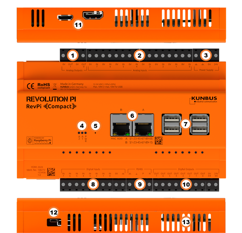
1 |
2 × analog output |
|
2 |
8 × analog input |
|
3 |
Power Supply |
|
4 |
3 × status LED |
|
5 |
Reset button |
|
6 |
2 × RJ45 Ethernet |
|
7 |
4 × USB A |
|
8 |
8 × digital input |
|
9 |
2 × RS485 |
|
10 |
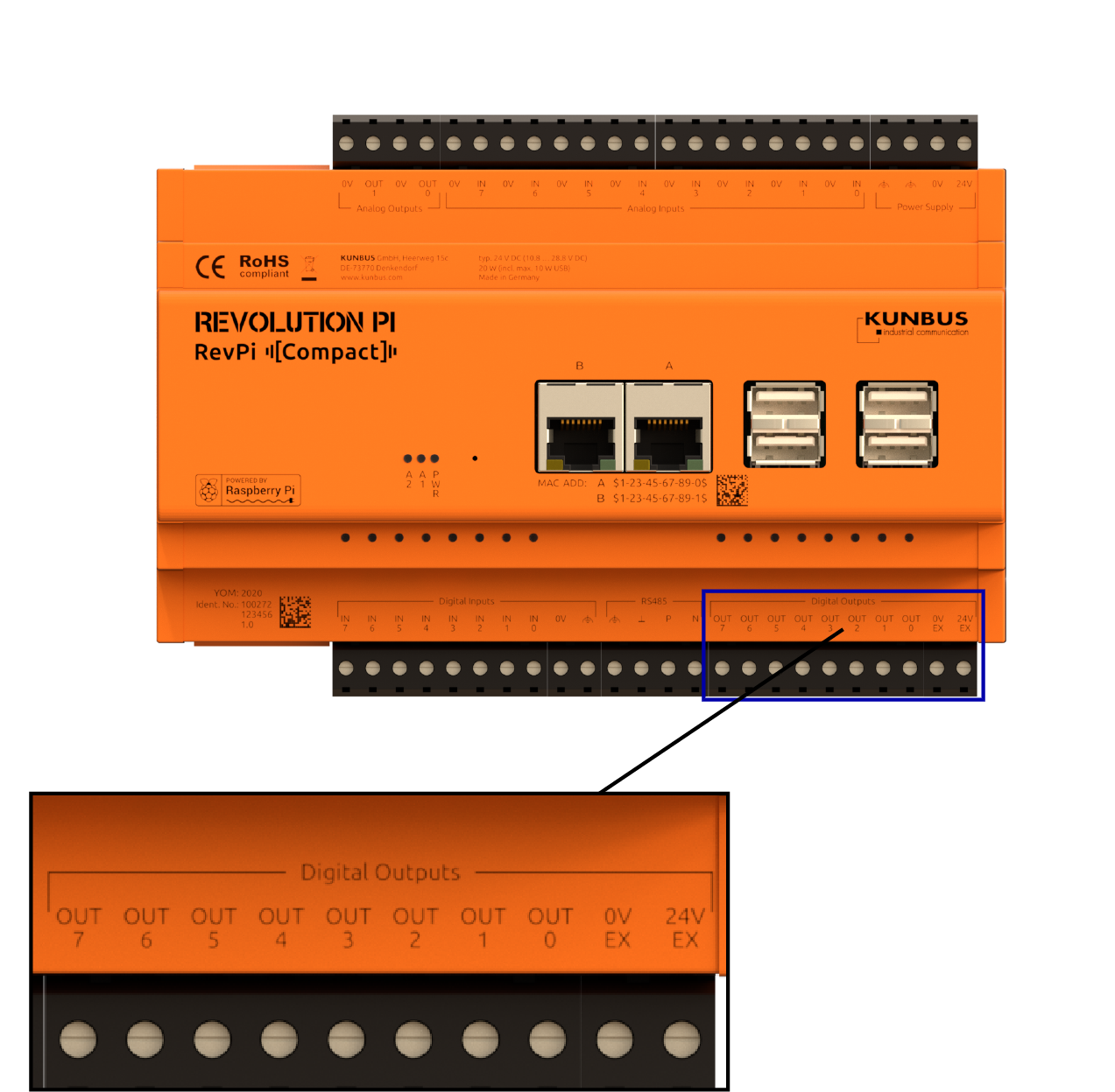
8 × digital output |
|
11 |
HDMI |
|
12 |
Micro-USB |
|
13 |
Ventilation Slots |
Compatible RevPi Image
-
RevPi Bookworm Image
-
RevPi Bullseye Image
-
RevPi Buster Image
-
RevPi Stretch Image
See: RevPi Images.
Virtual Devices #
The Virtual Devices are delivered with the RevPi image as components in PiCtory included:
Scope of Delivery #
The scope of delivery includes
-
RevPi Compact (non-modular base module)
-
4-pin plug Power Supply
-
4-pin connector Analog Outputs
-
4-pin plug RS485
-
10-pin connector Digital Inputs
-
10-pin connector Digital Outputs
-
16-pin connector Analog Inputs
-
Supplement
Mounting and Connecting #
The RevPi was developed for use in a control cabinet. Observe the specifications for the Intended Use and all Safety Instructions.
|
Warning
|
Danger to life due to electrical shock
There is a risk of fatal electrical shock when working on devices in the switch cabinet with 230 V mains voltage. ▷ Operations in the switch cabinet may only be carried out by qualified electricians. ▷ Before carrying out any operations in the switch cabinet, switch off the power supply properly. |
Carry out the installation and connection in the following order:
-
Mount your RevPi on a DIN rail.
-
Connect all other devices such as sensors and actuators. The interfaces available to you for this can be found in the Components section.
-
Connect a monitor and a keyboard if you want to operate the RevPi in desktop mode. This is not necessary if you can access the RevPi via a network connection.
-
As the last step connect the power supply
The digital outputs must be supplied with voltage separately via the 0V EX and 24V EX connections.
Access to the Device #
The RevPi is accessed in two steps:
Install all available updates as soon as the RevPi is connected to the internet, so that the system is always up to date with security-relevant features.
Alternatively, access is possible without a network, see Desktop Mode.
See also:
Reset Button #
The reset button restarts the RevPi.
▷ You can press the button by means of a thin object (e.g. a needle).
❯❯ The RevPi shuts down and restarts.
Configuration #
The RevPi is configured in two steps:
|
Note
|
Until the RevPi Bullseye Image (04/2024), the RevPi base module is configured via the RevPi Status application. |
-
From the RevPi Bookworm Image (10/2024), the basic configuration of the RevPi devices is carried out via the Cockpit web application:
-
Network configuration, user administration, status and log views can be managed via a browser.
-
In addition to the standard server configuration, the Revolution Pi and Node-RED plugins are also available. These allow you to configure your RevPi base module and easily activate or deactivate the installed services.
-
-
The module configuration of a Revolution Pi system, i.e. a RevPi base module with expansion modules, is carried out via the PiCtory application or, if necessary, directly in the development environment, e.g. via CODESYS.
|
Note
|
CODESYS and PiCtory cannot be used in parallel for configuration. An existing configuration via PiCtory will be overwritten by a configuration via CODESYS. The virtual devices OPC UA Server and MQTT Client can only be used via PiCtory. |
Parameterization #
The following parameters, inputs (INP), outputs (OUT) and memory variables (MEM) can be configured:
Core_Temperature (INP) #
Displays the CPU temperature as an integer value in degrees Celsius (°C).
Core_Frequency (INP) #
Displays the CPU frequency in MHz / 10, e.g. 2400 MHz = value 240.
DIn and DInBit_1 … 8 (INP) #
Displays the input values of the digital inputs, depending on the selected data schema:
-
BYTE: DIn
-
BOOL: DInBit_1 … 8
AIn_1 … 8 (INP) #
Displays the input values of the analog inputs.
DIn_Status (INP) #
Displays the status of the digital inputs.
DOut_Status (INP) #
Displays the status of the digital outputs.
AIn_Status (INP) #
Displays the status of the analog inputs.
AOut_Status (INP) #
Displays the status of the analog outputs.
RevPiLED (OUT) #
The freely programmable LEDs can be controlled via RevPiLED, see Configuring LEDs.
| Bit | Component | Status information |
|---|---|---|
|
1:0 |
LED A1 |
0000 = off |
DOut and OUT DOutBit_1 … 8 (OUT) #
Displays the output values of the digital outputs, depending on the selected data schema:
-
BYTE: DOut
-
BOOL: DOutBit_1 … 8
AOut_1 … 2 (OUT) #
Displays the output values of the analog outputs as an integer value.
AInMode_1 … 8 (MEM) #
Is the mode for the respective analog input:
-
Off
-
0 - 10V
-
PT100 Sensor
-
PT1000 Sensor
RS485 Serial Interface #
The RevPi has an RS485 interface to connect serial devices such as sensors.
The data lines of the RS485 socket are marked P (positive) and N (negative). For other devices, these lines are often referred to as D+ and D- or A and B.
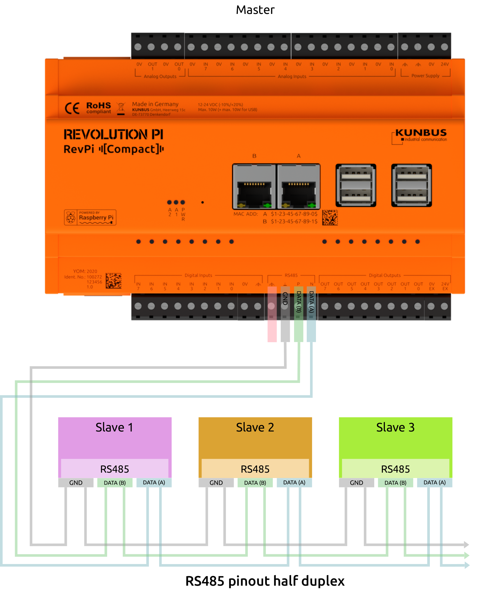
Wiring of the RS485 terminal:
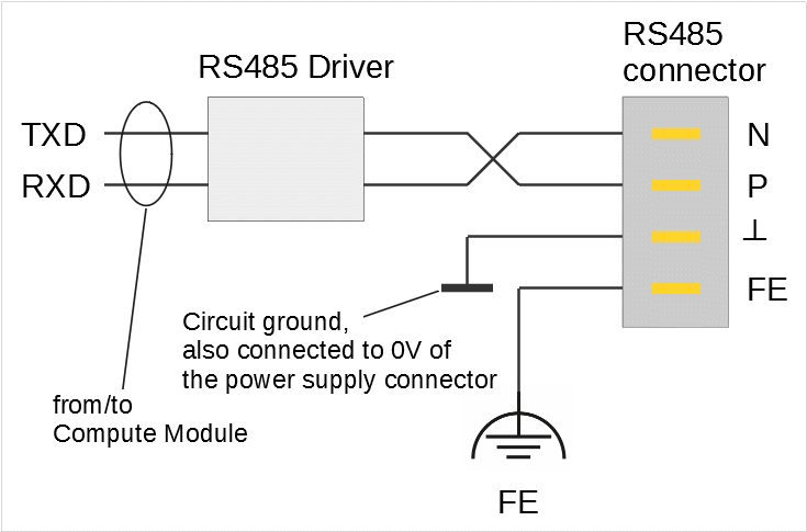
Only the lines N and P are required for the actual data transmission. We recommend to use a twisted pair for longer line lengths or higher bit rates.
If a reference potential should be necessary, you can use the electrical circuit ground at terminal ┴ for this purpose. However, you should not use this connection if it is not actually necessary. The cable shielding should ideally be connected to the FE terminal.
Cables having a length >30 m and cables leaving the building must be shielded. To improve the EMC properties of the shield, connect the shield to the grounded mounting plate over a large area using a conductive cable clamp. As an alternative, you can use a conductive EMC cable gland to lead the cable through the control cabinet wall.
Linux addresses the interface via the character device /dev/ttyRS485. You can configure bit rates up to 3,000,000. However, occasional reception errors may occur at more than 230,400 bps. The reason is that the UART of the Raspberry Pi, to which the interface is connected, has only a 16 byte FIFO and does not support DMA. The higher the bit rate, the more often the FIFO is not read out fast enough and received data is lost. For example, at 460,800 bps are 1- 2 errors per 50 MByte received, at 921,600 bps there are about 10 errors. If your RevPi Compact mainly sends data and only rarely receives it, you can also use higher bit rates. Otherwise we recommend to not set more than 230,400 bit/s.
Activating Termination Resistor
✓ The integrated 120 Ω terminating resistor of the RS485 interface is switched off after a restart.
▷ Start Cockpit and click on _Terminal in the menu to open the integrated terminal. Or log in to the RevPi via a terminal.
▷ Check out the Git repository of the command line tool rs485_config from GitLab with the command:
git clone https://gitlab.com/revolutionpi/rs485_config.git▷ Build the tool with the command:
cd rs485_config; make▷ Activate the resistor with the command:
./rs485_config <SERDEV> --set-bus-termReplace <SERDEV> with the name of the interface, e.g. /dev/ttyRS485.
▷ Check whether the resistor has been activated and display the settings of the RS485 interface with the command:
./rs485_config <SERDEV>❯❯ If the resistor is activated, Bus termination: Yes is output.
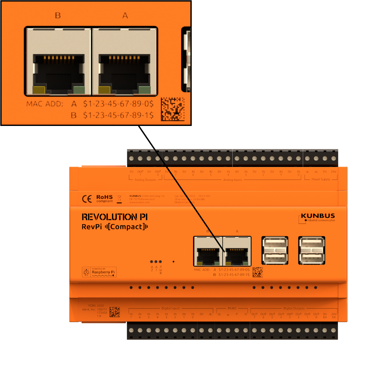
RJ45 Ethernet Interfaces #
The RevPi has two Ethernet Interfaces. Each of the two sockets is designed for different requirements.
Ethernet Interface A
You can achieve a maximum throughput of 11.2 MByte/s at this interface.
This Ethernet interface is connected to the internal USB bus. It has a maximum bandwidth of 480 MBit/s. Since all devices on the bus share this bandwidth, the throughput on this Ethernet interface may decrease if you connect many USB devices. You can address this interface in the software as eth0.
The MAC address for this Ethernet interface is printed on the housing and stored in the file /boot/config.txt. You can change the MAC address for eth0 here, if necessary. If no MAC address is entered in the file /boot/config.txt, e.g. because you have uploaded a new image, a unique MAC address is calculated from the serial number of the Compute Module.
Ethernet Interface B
This Ethernet interface is connected to the SPI bus (spi0). As a result, this interface shares the bandwidth with other devices you connect to the SPI bus.
You can achieve a throughput of up to 2.1 MByte/s at this interface. Even though this is slower than the Ethernet interface A, the Ethernet interface B is considerably robust against electromagnetic interference.
Please check if this interface is fast enough for your project. If you need a faster Ethernet connection for your project, we recommend to use interface A or combining both interfaces. This is explained in the following section.
You can address this interface in the software as eth1.
The MAC address for this Ethernet interface is printed on the housing and stored in the file /boot/config.txt. You can change the MAC address for the Ethernet interface B (eth1) here, if necessary. In addition, the MAC address is stored in a separate memory module of the Ethernet interface B (eth1). This factory MAC address is used if no MAC address is entered in the file /boot/config.txt, e.g. because you have installed a new image.
Combine Interfaces
To take advantage of both Ethernet interfaces, you can combine them into a virtual unit. It is called bonding. This allows to use the high bandwidth of the Ethernet interface A (eth0). In case of malfunctions on the USB bus, the system switches over automatically to the robust SPI interface.
Please note that it is not easy to connect both Ethernet interfaces to the same subnet without bonding. If you want to proceed in this way, you need to adjust the ARP configuration and it requires policy routing. However, since this is very complex, we do not recommend this method.
USB Interfaces #
The RevPi has 4 USB-A interfaces. This allows USB 2.0 client devices such as USB hard disks, surf sticks, keyboards or mice to be connected.
-
The inner sockets (4a) may be loaded with a maximum of 1 A each.
-
The outer sockets (4b) may be loaded with a maximum of 500 mA each.
-
The total load for all 4 USB interfaces must not exceed 2 A.
If more than four USB-A ports are required, a USB hub can be connected.
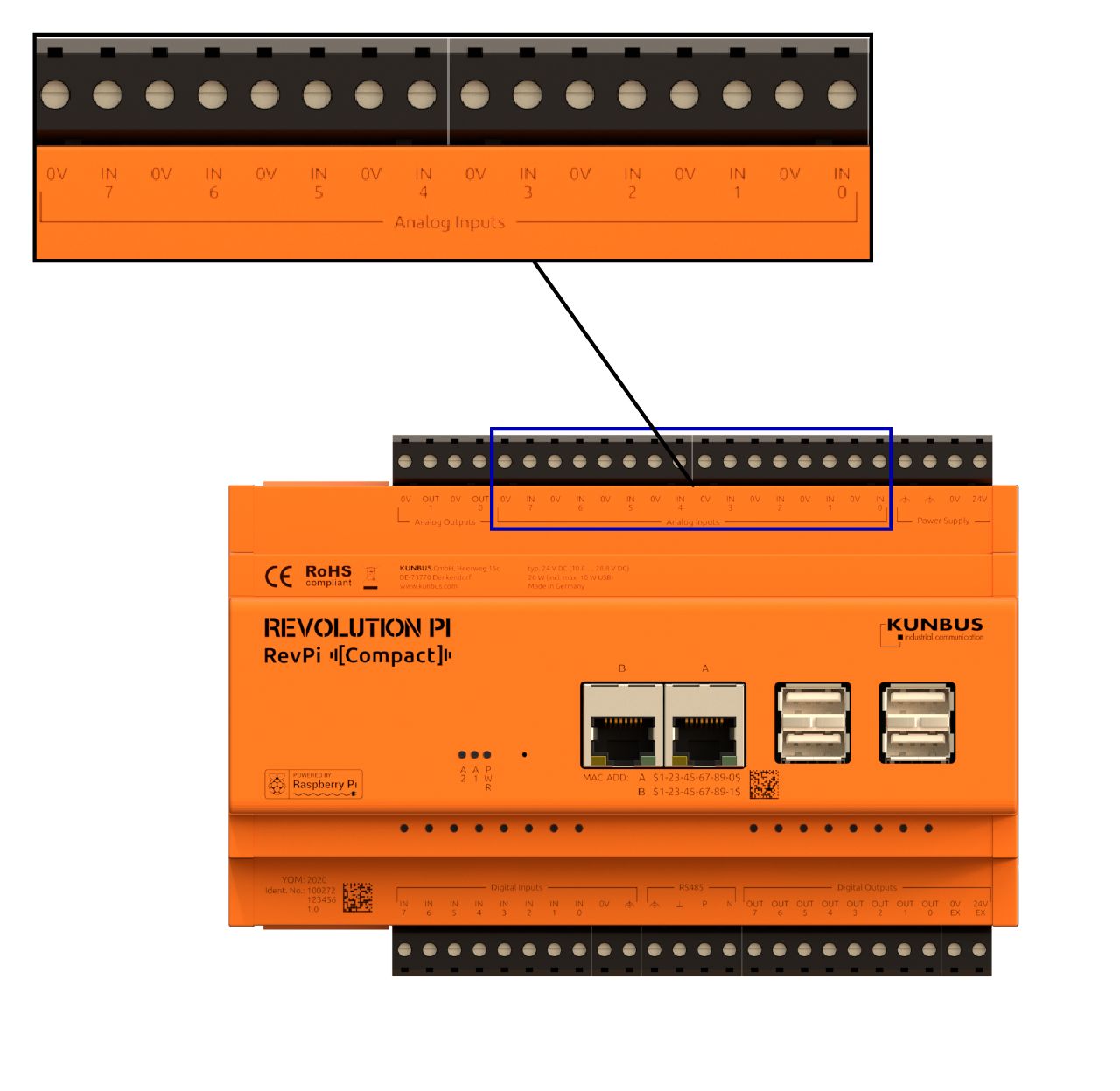
Analog Inputs and Outputs #
The RevPi Compact has eight analog inputs and two analog outputs.
Analog Inputs
You can measure a voltage between 0 and 10 V with each of the analog inputs or do a RTD measurement using a resistance temperature sensor (Pt100/1000). The analog input can also act as a constant current source. The Pt100/1000 sensor is connected directly to the analog input. Only a two-wire measurement can be made.
The MCP3550-50 analog-to-digital converter used for this purpose has a high resolution of 21 bits, but takes 85 milliseconds per measurement which is a comparatively long time. Another 40 milliseconds are required for switching the constant current source on and off and for switching the multiplexer, via which the eight inputs are connected to the ADC.
You can access the analog inputs either by using or not using piControl:
Using piControl, each input is read out with a cycle time of one second and stored in the process image as a 16-bit value in mV (for voltage measurement) or in 1/10 °C (for temperature measurement). Whether an input is used for voltage or temperature measurement is selected in PiCtory.
If piControl is not used, the cycle time for reading a single input is reduced to 125 milliseconds, and the raw value is available in full 21-bit resolution. You can calculate the values from this raw data.
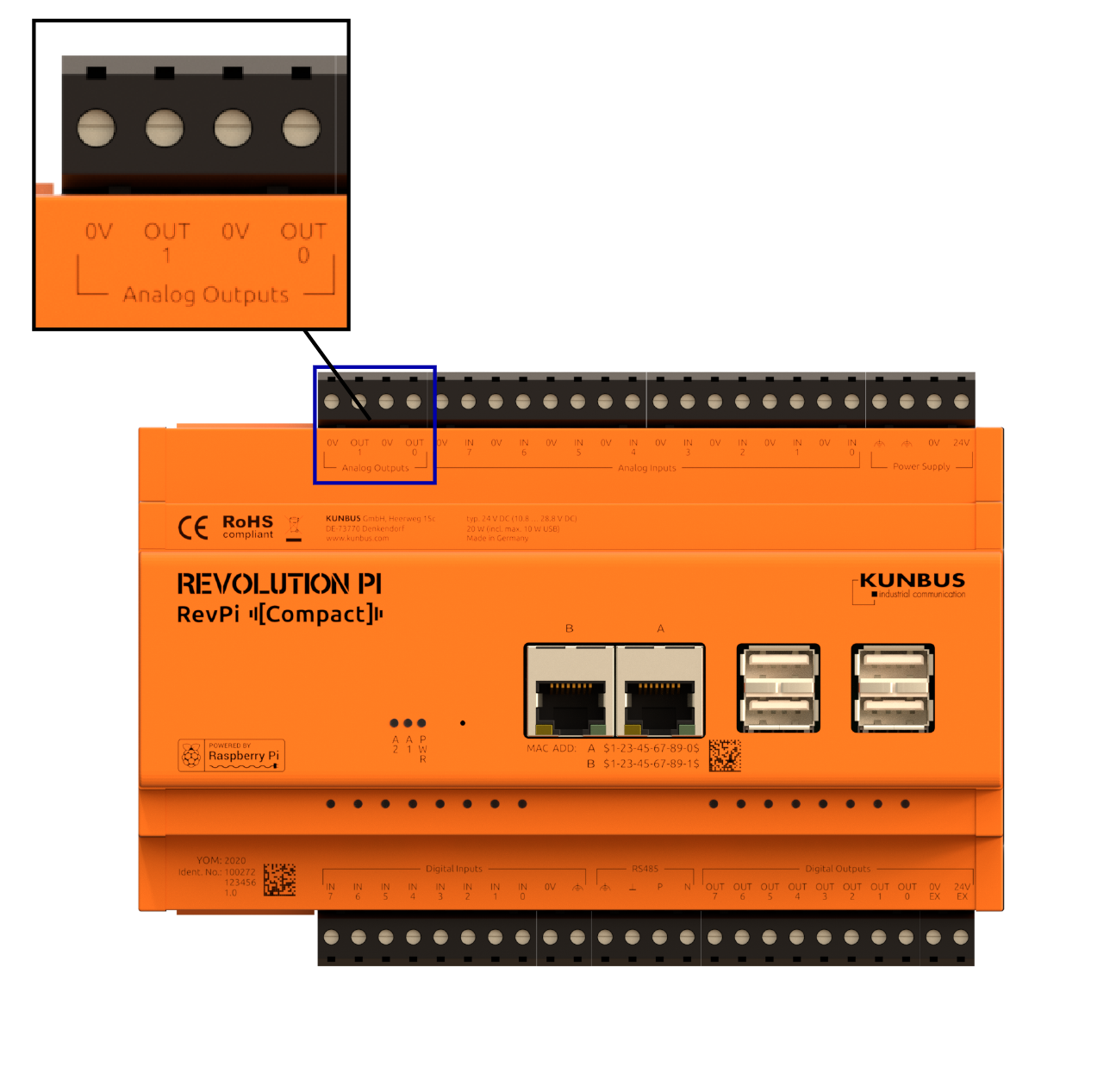
Analog Outputs
Your RevPi Compact has two analog outputs. They can output a voltage between 0 and 10 V. You can connect actuators such as frequency converters.
The DAC082S085 digital/analog converter used for this purpose has a resolution of 8 bits.
Similar to the analog inputs, you can access the outputs either by using or not using piControl: Using piControl the outputs are updated by the process image with a cycle time of 250 µs. You only have to store the required voltage in mV there. Not using piControl you can update the outputs at any time. However, you have to calculate then the raw value in 8-bit resolution from the required voltage yourself.
There are three options for powering down the analog outputs: terminated with 2.5 kΩ, with 100 kΩ or high impedance. The powerdown can only be used for both outputs together and only by not using piControl.
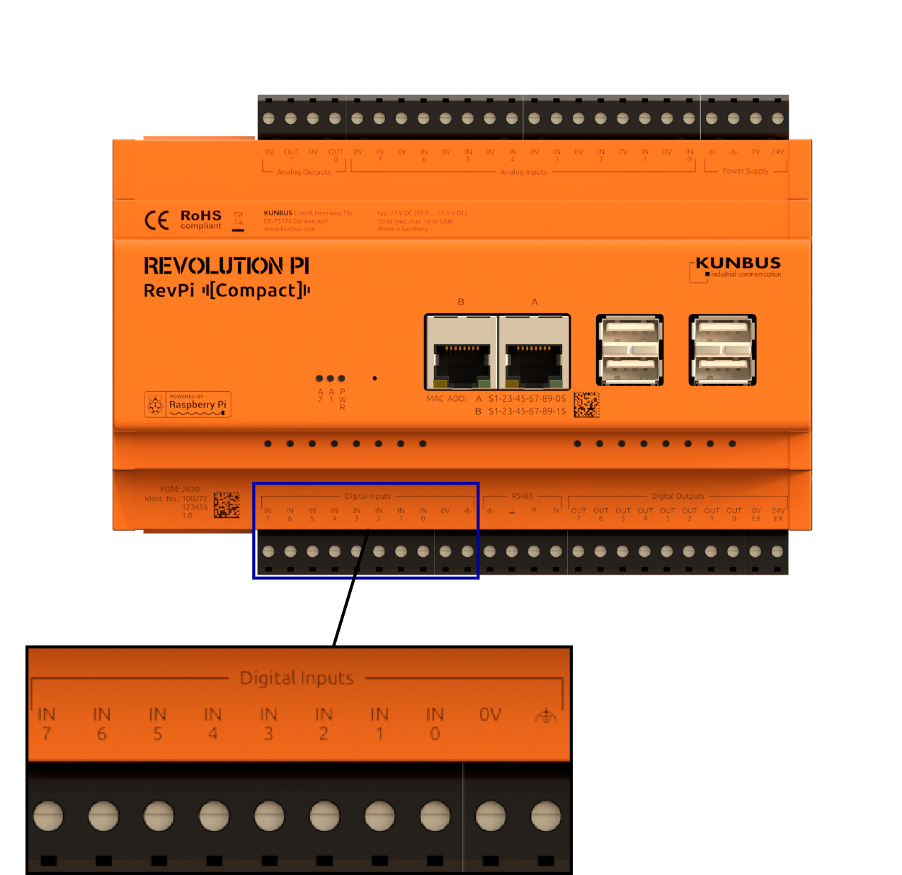
Digital Inputs and Outputs #
The RevPi has eight digital inputs and eight digital outputs.
You can access them either with piControl or without piControl. With piControl they are synchronized cyclically with the process image every 250 µs.
Digital Inputs
The digital 24 V inputs are supposed to forward signals to the controller that are e. g. determined by a sensor.
The inputs are designed for voltages up to 36 V.
-
The switching threshold up to which low is guaranteed to be measured is 7 V.
-
High is guaranteed from 10.2 V.
The inputs are not isolated galvanically. A separate terminal is available for connecting the ground.
The LEDs above each digital input light up if the input is high.
Debouncing can be carried out in four stages: 25 µs, 750 µs, 3000 µs or no debouncing. The debouncing can only be set jointly for all eight inputs.
The inputs are able to detect an excess temperature (135°C): a warning is then issued in the kernel log and a status bit is set in the piControl process image.
Digital Outputs
Unlike the inputs, the eight digital 24 V outputs are isolated galvanically .
The digital outputs must be supplied separately with a voltage of 12 … 36 V via the 0V EX and 24V EX connections. Always use the same ground potential that supplies the connected sensors or actuators.
The digital outputs are protected by an automatic switch-off in case of excess temperature. This switch-off applies separately to each individual output.
The LEDs above each digital input light up if the output value is high.
The outputs are monitored by a watchdog and set to low if they are not rewritten every 9 ms. This ensures that the outputs are brought into a safe state, for example in the event of a system crash. In this case the LEDs do not light up any longer. However, this monitoring only works if the outputs are not set with piTest or piControl, but the GPIOs are written directly. The background is that the output in piControl is held at 1 by a loop until the output is actively set to 0.