This Tutorial explains how to configure a RevPi base module as a Modbus RTU Slave using a USB-RS485 Converter. It includes detailed steps to set up the connection and query data from the RevPi using a Modbus RTU Master.This Tutorial is for industrial automation professionals, IoT developers, and others needing to integrate RevPi as a Modbus RTU Slave in their systems.
Prerequisites #
Hardware
✓ RevPi base module (eg.RevPi Connect 4)
✓ Master device or software, e.g. QModmaster on a Windows PC.
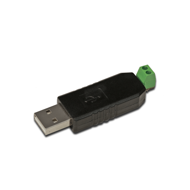
✓ USB-RS485 Converter
✓ Cables and connectors for RS485 communication
Software
✓ Modern web browser (e.g. Google Chrome or Mozilla Firefox). ✓ QModmaster: downloadable from SourceForge.
RS485 Signal Connections
| Signal | Pin |
|---|---|
RS485- |
D+ |
RS485+ |
D- |
Step 1: Setting up the Hardware #
▷ Connect the USB-RS485 Converter to the RevPi Connect.
▷ Wire the RS485+ and RS485- signals appropriately to your devices.
▷ Ensure power is supplied to the RevPi Connect.
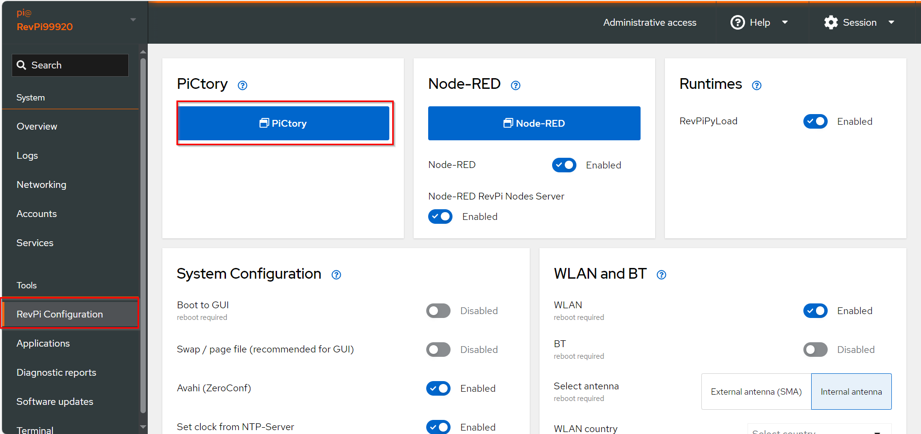
Step 2: Configuring Modbus RTU Slave in PiCtory #
▷ Add the base module and the virtual Modbus RTU Slave to your configuration, see Arrange Devices.
▷ Drag the base module from the Device Catalog onto the virtual DIN rail.
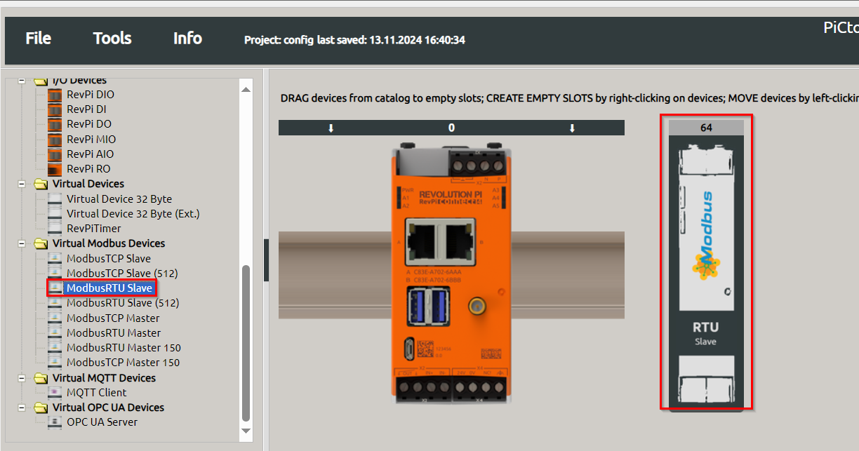
▷ Open the folder Virtual Devices in the Device Catalog.
▷ Drag Modbus RTU Slave to the base module on the virtual DIN rail.
❯ The Modbus RTU Slave will now appear in the configuration.
▷ Configure Modbus TCP Slave, see Configuring Inputs and Outputs
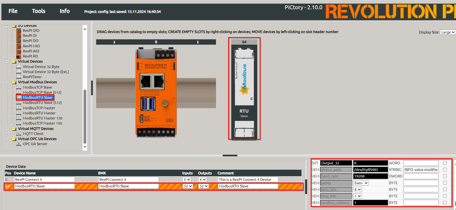
▷ Select the Modbus RTU Slave in the configuration.
▷ Set the following parameters in the Value Editor:
| Parameter | Description |
|---|---|
Input |
Configure up to 32 input values, each 16 bits wide. |
Output |
Configure up to 32 output values, each 16 bits wide. |
device_path |
Path to the Linux device file, default: |
baud_rate |
Speed of the serial connection, default: |
parity |
Configure parity bit: None, Even (default), or Odd. |
data_bits |
Number of data bits, default: |
stop_bits |
Number of stop bits, default: |
|
Note
|
If using multiple devices of the same type, configure unique udev rules to prevent device path conflicts after reboot. |
▷ Save the configuration and restart the driver to apply the changes.
Step 3: Querying Data Using QModMaster #
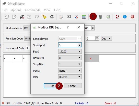
▷ Start QModmaster on the Windows PC.
▷ Set the parameters baud rate, parity, stop bits and data bits for communication to match the Modbus RTU Slave configuration.
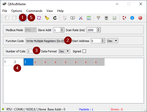
▷ Use QModmaster to write values (e.g., 1, 2, 3) into the Modbus registers.
▷ Use the piTest command to query data from the Modbus RTU Slave:
piTest -1 -r Input_1Example Output:
2 Byte-Value of Input_1: 1 dez (=0001 hex)
piTest -1 -r Input_2
2 Byte-Value of Input_2: 2 dez (=0002 hex)
piTest -1 -r Input_3
2 Byte-Value of Input_3: 3 dez (=0003 hex)|
Note
|
Ensure the master and slave devices are configured with matching baud rates for proper communication. |