This tutorial explains how to configure the RevPi Connect 4 as a Modbus TCP Slave and control an LED through the digital output of the RevPi DIO. The Modbus TCP Master is simulated using QModMaster, and a Python script leveraging the RevPiModIO library is developed to transfer Modbus data to the digital outputs.
Prerequisites #
Hardware
✓ RevPi base module (eg. RevPi Connect 4)
✓ Master device or software: e.g. QModMaster running on a Windows PC.
✓ Matching cables with RJ45 connectors
✓ Power supply for RevPi Connect
Software
✓ Modern web browser (e.g. Google Chrome or Mozilla Firefox)
✓ QModMaster: Downloadable from SourceForge for use in this example
Setting up the System
Ensure that:
✓ the RevPi base module and master device are located in the same network.
✓ IP addresses are properly configured, and the devices can communicate with each other.
Step 1: Setting up the Hardware #
▷ Connect the RevPi Connect to the master device using an RJ45 cable.
▷ Power on the RevPi Connect by connecting it to a suitable power supply.
Step 2: Configuring Modbus TCP Slave in PiCtory #
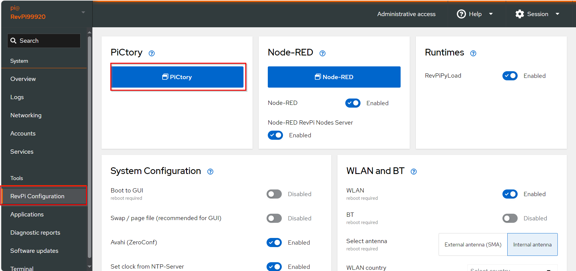
▷ Add Base Module and Add the virtual Modbus TCP Slave to your configuration, see Arrange Devices.
▷ Drag the base module from the Device Catalog onto the virtual DIN rail.
▷ Open the folder Virtual Devices_ in the Device Catalog.
▷ Drag Modbus TCP Slave to the base module on the virtual DIN rail.
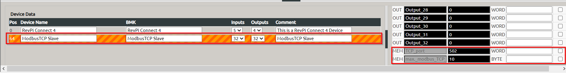
❯ The Modbus TCP Slave will now appear in the configuration.
▷ Configure Modbus TCP Slave, see Configuring Inputs and Outputs.
▷ Select the Modbus TCP Slave in the configuration.
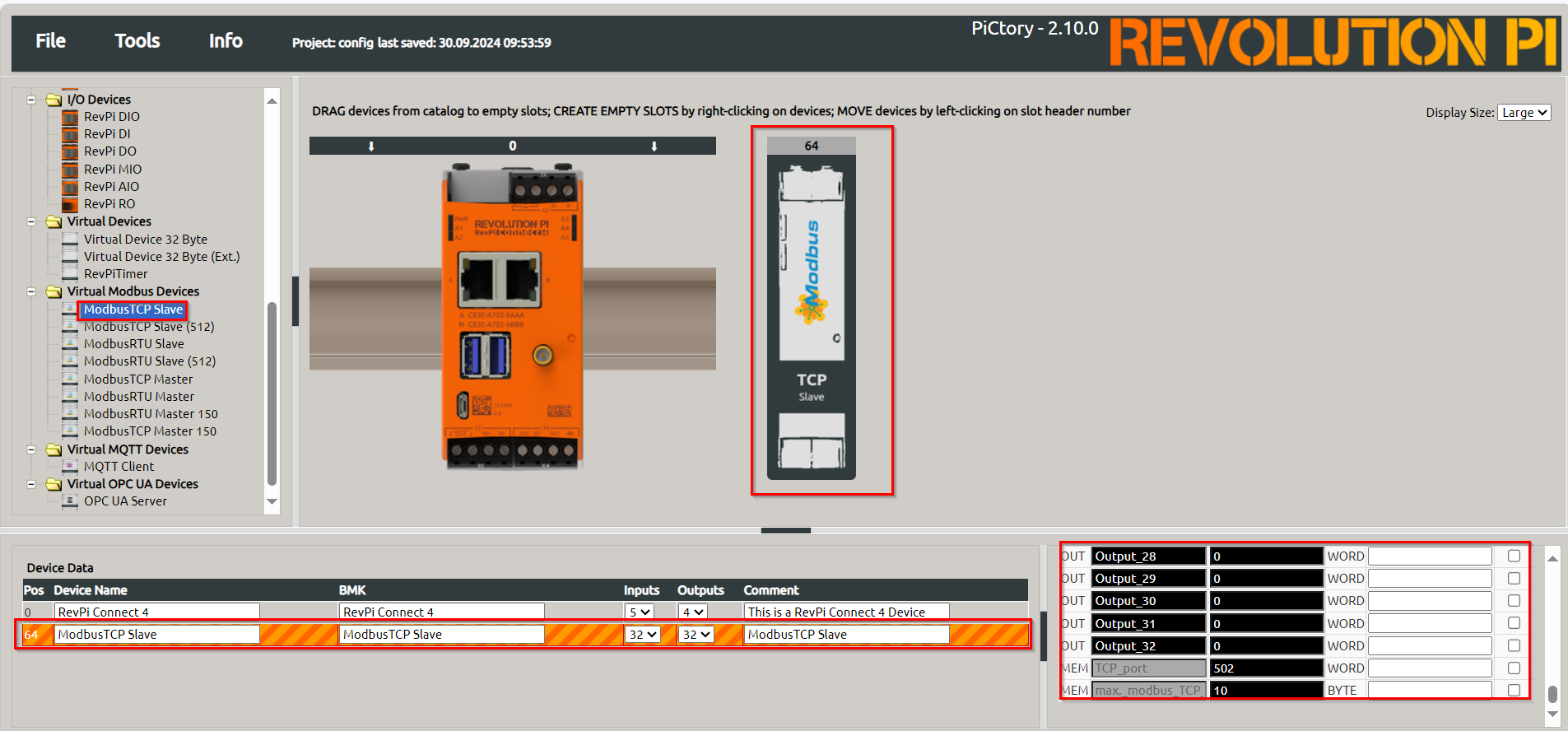
▷ Set the following parameters in the Value Editor:
-
TCP Port:
502(default value according to the Modbus specification) -
Max. Modbus TCP Connections:
10(or other suitable value) -
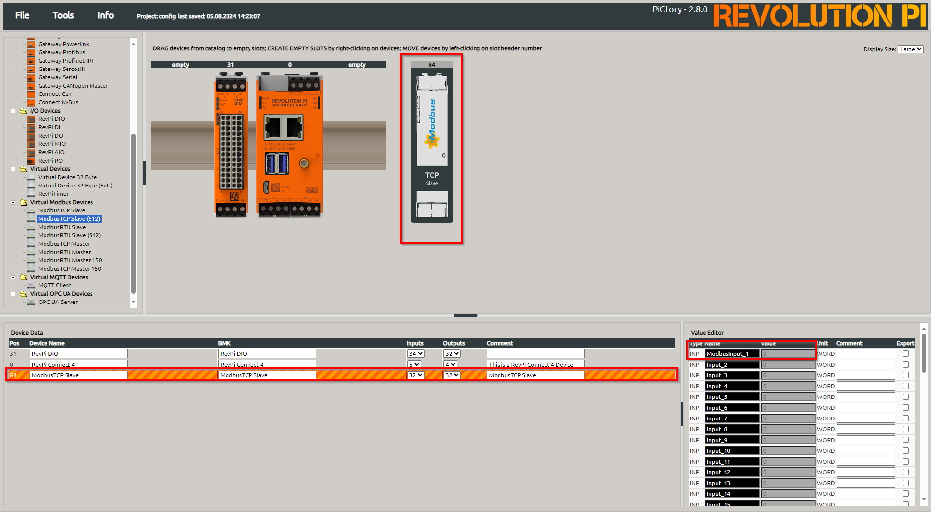
Input_1→ModbusInput1 -
Output_1→ModbusOutput1
▷ Save the configuration and restart the driver to apply the changes.
Step 3: Preparing the Hardware #
▷ Connect the RevPi Connect 4 to the RevPi DIO via the PiBridge.
▷ Attach an LED to one of the digital outputs of the RevPi DIO (e.g. RevPi DIO Output 1 oder O_1).
Step 4: Setting up QModMaster #
Installing QModMaster
▷ Download QModMaster from its official website and install it on your computer.
Establishing Connection
▷ Start QModMaster.
▷ Navigate to and enter the following details:
-
IP Address: IP address of the RevPi Connect 4
-
Port:
502(default for Modbus TCP)
▷ Confirm the settings and establish the connection.
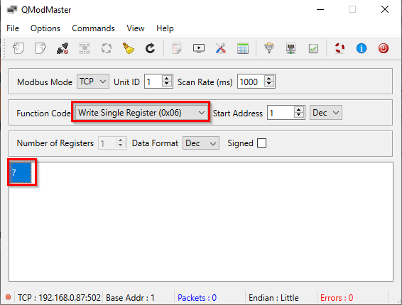
Sending Modbus Data
▷ In QModMaster, select the function Write Single Register (0x06).
▷ Enter the address of the first Modbus register (e.g., address 0).
▷ Write the value 7 (equivalent to 0b0000111) to set the first three digital outputs (RevPi DIO) to HIGH.
Step 4: Creating and Uploading a Python Script Using RevPiModIO #
Creating the Python Script
▷ Write the following Python script to process Modbus data and control the LED:
import revpimodio2
import time

# Initialize the RevPiModIO object
rpi = revpimodio2.RevPiModIO(autorefresh=True)

while True:
    # Set ModbusOutput1 value to the value of I_1
    rpi.io.ModbusOutput_1.value = int(rpi.io.I_1.value)
    # Set O_1 value to the value of ModbusInput1
    rpi.io.O_1.value = int(rpi.io.ModbusInput_1.value)

    # Print current values for verification
    print(f"ModbusOutput_1: {rpi.io.ModbusOutput_1.value}, O_1: {rpi.io.O_1.value}")

    time.sleep(0.02)
Transferring the Script to the RevPi
There are two ways to upload the script:
Option 1
▷ Use RevPiCommander.
Option 2
Manually via Terminal:
▷ Open a terminal on the RevPi or connect via SSH.
▷ Create the script using the following command:
sudo nano Revpi_DIO_Modbus.py▷ Paste the script code and save the file.
▷ Run the script with:
python3 Revpi_DIO_Modbus.pySummary #
In this tutorial, you learned how to configure the RevPi Connect 4 as a Modbus TCP Slave, control an LED using the RevPi DIO, and send data via QModMaster. The Python script utilizes the RevPiModIO library to transfer Modbus data to the RevPi DIO outputs.
Now, the first three digital outputs should activate when the value 7 is sent to the Modbus register, making the LED light up.