This tutorial demonstrates how to configure Modbus TCP and Modbus RTU masters on a RevPi Connect+ with CODESYS Control CODESYS Control for Linux ARM or ARM64. The application reads the holding registers (0 … 9) of connected Modbus slaves and writes their values back to holding registers (10 … 19).
Prerequisites #
Hardware #
✓ RevPi Connect+
✓ One Modbus TCP slave
✓ One Modbus RTU slave
For detailed instructions about how to set up your system, see Getting Started.
Software #
✓ CODESYS Development System installed on your PC
To ensure a compatible system with suitable software, see Software Compatibility.
Overview #
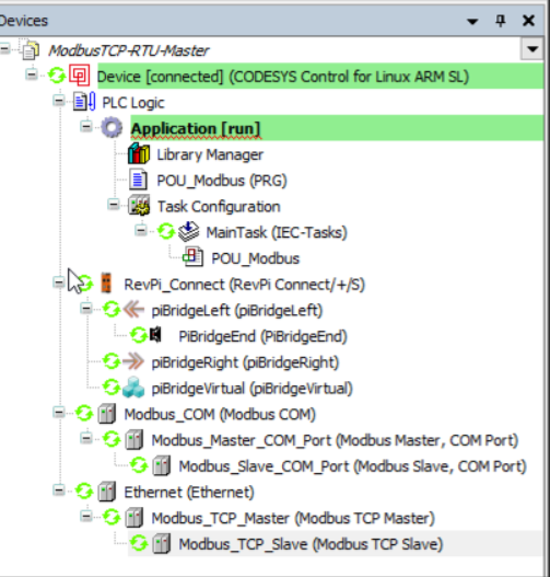
The device tree in CODESYS is configured with:
-
Modbus TCP Master: Reads and writes to a TCP slave device.
-
Modbus RTU Master: Communicates with a serial RTU slave device.
-
POU_Modbus: Handles the application logic for reading and writing data.
Adapting for RevPi Core or RevPi Compact
To adapt the project for RevPi Core or RevPi Compact:
▷ Open the context menu of RevPi Connect in the CODESYS device tree.
▷ Select Update device.
▷ Choose RevPi Core or RevPi Compact as the replacement and rename the device accordingly.
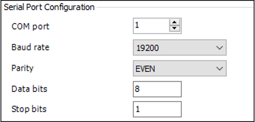
Step 1: Configuring Modbus RTU Serial Port #
For RevPi Connect or RevPi Core
▷ Edit the configuration file:
sudo nano /etc/CODESYSControl_User▷ Add the following line:
[SysCom]
Linux.Devicefile=/dev/ttyUSB
▷ Map the COM ports in CODESYS as follows:
/dev/ttyUSB0 → COM port 1
/dev/ttyUSB1 → COM port 2
** /dev/ttyUSBn → COM port n
If an extra USB-485 converter is connected, the correct COM port has to be identified.
For RevPi Compact
▷ Edit for the default RS485 Port /etc/CODESYSControl_User and add:
   [SysCom]
   Linux.Devicefile=/dev/ttyAMA
▷ For using the USB-485 converter add the following line instead:
   [SysCom]
   Linux.Devicefile=/dev/ttyUSB
Step 2: Configuring Modbus RTU Slave #

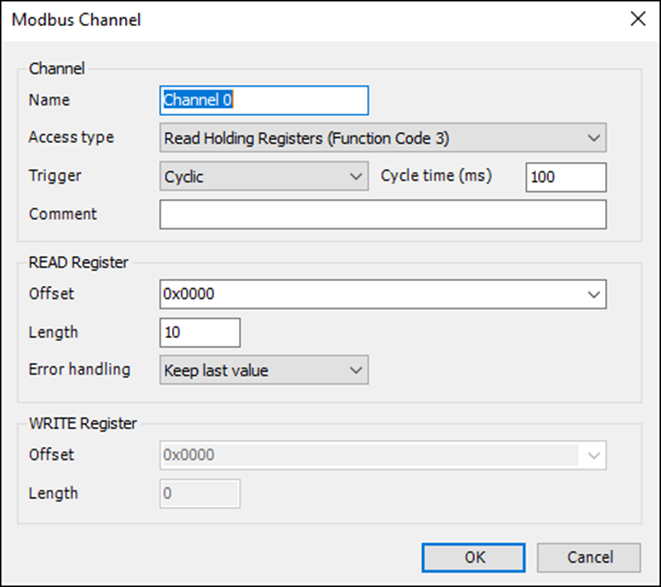
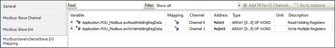
▷ Set up the RTU slave with:
-
Channel 1: Read Holding Registers
-
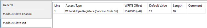
Channel 2: Write Multiple Registers
▷ Ensure the default values for the first 10 holding registers are 12.
▷ Map these channels in the POU_Modbus logic for application-level access.
Step 3: Configuring Modbus TCP Slave #
▷ Specify the Modbus TCP Slave Address in the CODESYS configuration.
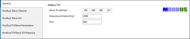
▷ Use the same mapping logic as Modbus RTU for holding registers 0 … 9 and 10 … 19.
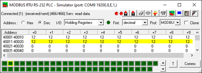
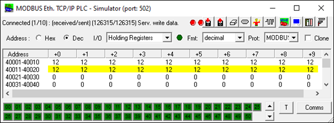
Step 4: Simulating Modbus Slaves #
To simulate Modbus TCP and RTU slaves, use ModRSsim2:
▷ Download the application from ModRSsim2 on SourceForge.
▷ Configure Modbus TCP/RTU slaves to have holding registers: 40001 … 40010 for source data 40010 … 40020 for destination data
Step 5: Deploying and Testing #
▷ Download the compiled project to the RevPi device.
▷ Run the application on your RevPi base module.
▷ Verify that:
-
Data is correctly read from holding registers 0 … 9.
-
Data is written back to holding registers 10 … 19.
|
Note
|
Default RTU Slave Configuration |
|
Note
|
Debugging |
|
Note
|
Simulation |
This setup allows Modbus TCP and RTU masters to operate simultaneously, enabling robust data exchange with Modbus-enabled devices.